Well, my first mistake in the project. I don’t know why I didn’t read this correctly, but my Pitot module does not deliver PWM but Analog signal between 0 and 5V. The NAVIO+ board has four analog inputs, two of them are used by the power module (one for battery voltage, one for current), so I have two left. The problem is, it must be max 3.3V and the Pitot delivers 5V.
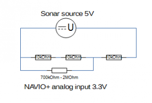
Goal is to convert 5V to 3.3V at insignificant current. The easiest is to use resistors to divide the voltage, since 3.3V is 2/3 of 5V, three resistors of identical value in serial will divide the voltage by 3. Plug over two, you’ve got 2/3. The only problem is which resistor value to choose. The internal resistance of the analog input of the NAVIO+ board is between 700kOhm and multiple MOhm. So the resistors use must be significantly lower than that to avoid any influence of the input impedance. But if your resistors are too lower, the Pitot module will not be able to deliver the current. The Pitot module can deliver at least 1mA.
Remember U = R * I ? (U=Volt, R=Ohm, I=Ampere).
5V = ? * 0.001A => 5 / 0.001 = 5kOhm (all three together)
On the other side, to avoid any influence from the variable impedance of the analog input, the resistors should be at least 50 times lower. 700kOhm / 50 = 35kOhm (value of two resistors).
5000 / 3 < my_resistor < 35000 / 2
So I’ve chosen arbitrarily the value of 10kOhm.
If you haven’t followed the logic, maybe this little drawing helps.
Finally we have the following:
Max Input: 5V
Max Output: 3.3V
Max Current: 0.17mA
Max Dissipated energy: 0.85mW
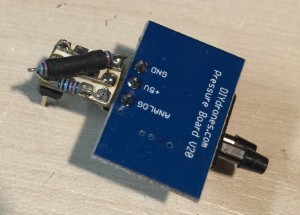
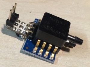
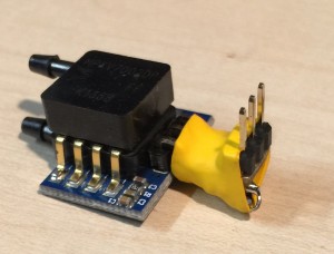
Here a few pictures of the adapter. I’m not especially proud of the board and soldering but I haven’t done real electronics (with appropriate tools) for a while.